Chemical Dosing System
EnquiryContact us to get !
- Free design suggestions
- Product Technical details
- Full product catalog
.
Product Description
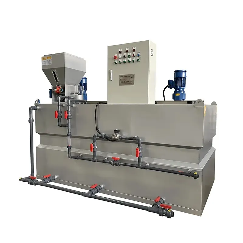
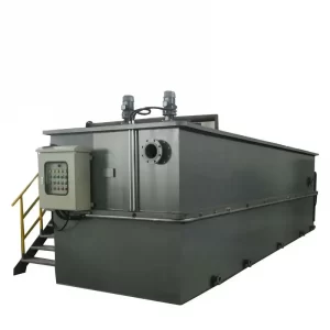
The automatic dosing device is mainly used for the treatment of boiler feed water, circulating water, hydrazine, phosphate, etc. in power plants, and can also be used in petroleum, chemical, environmental protection, water supply systems and other industries. The unit combined dosing device mainly includes a solution tank, a metering pump, a filter, a safety valve, a check valve, a pressure gauge, a buffer tank, a liquid level gauge, and a control cabinet, which are integrated and installed on a base.
Machine working process
- Under the control of the electric control cabinet, the clean water and the dry powder in the powder box are put into the wet and dry mixer on time and at a fixed speed, and after the two are initially mixed, they are injected into the main tank of the automatic dosing device.
- The main tank is generally divided into three, namely the prefabricated tank, the curing tank and the storage tank. Each tank is equipped with a stirrer, and the tanks are separated by a baffle that is lower than the height of the tank.
Make the liquid fully stirred in the first tank and then overflow
into the next slot. - The clear water and the medicinal powder are fully mixed by stirring in the three tanks to gradually generate the required medicinal liquid, and the medicinal liquid is stored in the storage tank. With the use of screw pumps and pipelines, the liquid medicine can be delivered to the equipment that needs to be added.
Specification
| Model/Parameter | JY500 | JY1000 | JY1500 | JY2000 | JY3000 | JY4000 | |
| Capacity(L/H) | 500 | 1000 | 1500 | 2000 | 3000 | 4000 | |
| Dimension(mm) | 900*1500*1650 | 1000*1625*1750 | 1000*2240*1800 | 1220*2440*1800 | 1220*3200*2000 | 1450*3200*2000 | |
| Powder Conveyor Power N(KW) | 0.37 | 0.37 | 0.37 | 0.37 | 0.37 | 0.37 | |
| Paddle Dia(mm)φ | 200 | 200 | 300 | 300 | 400 | 400 | |
| Mixing Motor/Spindle Speed n (r/min) | 120 | 120 | 120 | 120 | 120 | 120 | |
| Power N(KW) | 0.2*2 | 0.2*2 | 0.37*2 | 0.37*2 | 0.37*2 | 0.37*2 | |
| Inlet Pipe Dia DN1(mm) | 25 | 25 | 32 | 32 | 50 | 50 | |
| Outlet Pipe Dia DN2(mm) | 25 | 25 | 25 | 25 | 40 | 40 |

